Wednesday, August 10, 2022

Import Expression and the Scanned Morph Database

Update August 26, 2022

There has been some improvements since this post was originally written. First of all, the name of the button has changed; it is now called Import Expression rather than Import Morph. This reflects the typical usage: you typically import an expression from a directory called Expressions, and a pose from a directory called Poses. However, both Import Pose and Import Expression can import both poses and expressions.

There are now two buttons in the Morphs section:

Scan Morph Database works as before, and the new Check Database For Updates checks if you have installed any new morphs since the last time the database was scanned.
We can either choose to check all characters, or the active mesh, or specify which databases we need to check.
We get a list of characters where new morphs have been installed since the last scan.
As mentioned above, the import tool has been renamed to Import Expressions
  • Affect Bones: If enabled, poses are imported as well as morphs. 
  • Clear Morphs
  • Use Scanned Database:
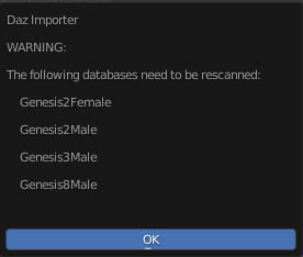
  • Check For Updates: Check if the database for the active character needs to be rescanned because new morphs have been installed. Can be disabled if you know that the database is up-to-date.
  • Load Missing Morphs
  • Category: Loaded custom morphs are put in this category. Defaults to Loaded.
  • Make All Bones Posable: If any loaded morphs has made bones driven.
  • Affect Geografts:
  • Auto Keying: Automatically insert keyframes at the current frame.
And the expression is loaded.


Original post:

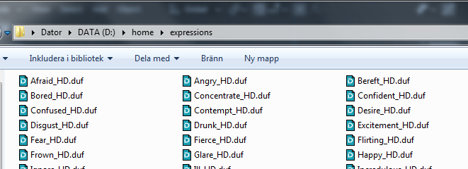
Morphs lead to problems. On the one hand we want to load lots of them, so they are available when we need them. On the other hand we run into serious performance problems when many morphs are loaded. It takes a long time to load many morphs, and a character with many loaded morphs becomes very sluggish when we animate. Also the user interface lacks visual cues (how do the morphs BEF01, BEF02, etc look?), and in the end we had probably forgotten to load the morph we needed anyway.

Why there is a performance problem is not a mystery. All drivers have to be recalculated every time the viewport is updated, and there are a lot of drivers if many morphs are loaded. It can be avoided with the Disable Drivers button, but that can only be done while we pose the character, not when we tweak the morphs.

But it doesn't have to be that way. Many custom morphs are simply combinations of basic morphs, either the face units or the FACS morphs, so it should be enough to load those. In the latest development version we can do just that.

The first step is to scan the entire DAZ Studio database and store the morph information for later use. The button that does this is called Scan Morph Database and is located in the Setup > Morphs panel. Since scanning the database can take a lot of time, only files related to the active mesh are scanned by default.

However, if we disable Scan Active Mesh, we can specify which characters to scan.

Scanning the database can take a long time, but fortunately it only has to be done once. Or every time new morphs have been installed on your system. Take a cup of coffee while the computer works.

When the scanning process is completed we import morphs with the new Import Morph button in the Posing panel.

Select the expression in the file selector.

And the expression is loaded. Keyframes are created if Auto Keying is enabled.

Note that the expression is always loaded at 100%. There is no slider that we can adjust if we want to reduce the strength of the morph, but if we loaded the morph with Auto Keying enabled we can achieve similar results by scaling the F-curves.

Since there now is a separate tool for loading morphs, the Load Pose tool no longer affects morphs by default. Instead we load poses and expressions in two separate steps. This is normally not a big deal since they are usually defined in separate files anyway.

And here is a combination of a pose and an expression.

Monday, August 8, 2022

Changes to the MHX rig

Recently there were some changes to how the MHX rig is controlled. 

  • Previously it was controlled by a mix of RNA and id properties (the difference is explained in more detail below), now only (API defined) RNA properties are used. Whereas you could argue which is the best choice, mixing the two types of properties was very confusing, e.g. because they are animated separately.
  • Previously MHX used armature properties, now it uses object properties. In order to use armature properties in a linked file, they had to be made both library overridable and library editable, whereas object properties only need to be library overridable. And armature RNA properties could not be keyframed at all.
  • Stretchiness is now controlled by the floating point influence rather than the boolean enable, to make animation smoother. Other control may be converted into float properties in the future for the same reason.

This may sound technical, but the changes should not alter the panels and the behaviour very much, at least after engetudouiti pointed out all the bugs that I introduced in the process. It means that MHX rigs generated with previous versions do not work. However, they can be updated to the latest version with the Update MHX button that appears in all MHX panels. Note that the update is irreversible, so if you have a scene that works with a previous version of the MHX RTS it might be better to stick to that. Another possibility, which I favour myself, is to keep a file with the original genesis character around, and regenerate the MHX rig from scratch.

RNA and id properties

An RNA property is defined by the python script when is loaded, and it is available for all data of a given type. An id property is defined dynamically at runtime, and is only defined for a single datum. An example of id properties are the morphs, which are loaded at runtime. Different characters can have different sets of morphs, although they are all armature objects. Hence morphs must be id properties.

Let us compare how the two types are accessed in Python. First RNA properties. They are defined by a statement like this (the last line makes the property accessible in a linked file).

bpy.types.Object.RNA_property = bpy.props.FloatProperty(
    name = "RNA Property",
    description = "RNA Property",
    default = 0.0,
    override={'LIBRARY_OVERRIDABLE'})

    
To access an RNA property, we use getattr, setattr, or the dot notation, e.g.

    setattr(ob, "RNA_property", 0.5)
    ob.RNA_property = 0.5

    
Id properties don't have to be defined at all, they are just assigned and then they exist.

    ob["id_property"] = 1.0
    
A limitation with id properties is that they can only be floats, integers, or strings, but not booleans, enums, vectors, or collections. So instead of a boolean, we could use an integer property limited to the range [0,1]. This works in principle, but an integer is displayed as a slider rather than a checkbox. Since that is ugly, the old MHX RTS displayed the RNA property (a true boolean) rather than the id property (an integer).

But then came the next problem. Armature RNA properties don't seem to be animatable. So if you right-clicked on a float property like Gaze Follows Head (an id property since a float is natually displayed as a slider), you could set a keyframe, but if you right-clicked on a boolean property like Left Arm Stretch (an RNA property), keyframing was not available.

 
OK, so this was confusing? The bottom line is that by consistently using object RNA properties, all problems went away. Properties are animatable, booleans display as checkboxes, and everything works with file linking. At least after all bugs have been ironed out.

Friday, June 24, 2022

TONE MAPPING

This post is requested by Midnight Arrow at bitbucket to explain tone mapping in relation to material conversion. Below there's some reference.

http://www.digitaldog.net/

https://docs.omniverse.nvidia.com/app_create/prod_materials-and-rendering/render-settings_post-processing.html

https://docs.blender.org/manual/en/latest/render/color_management.html

https://bitbucket.org/Diffeomorphic/import_daz/issues/22/basic-tone-mapping


One feature of the diffeomorphic importer is that it converts materials from iray to cycles and eevee. This means that you can reasonably expect that your blender materials will be similar to daz studio. Then lights and cameras are converted as well, together with the notorious ghost lights. So your daz scenes will mosttly retain in blender the same look they have in daz studio.

What is not converted is tone mapping. Because there's no easy way to do it, and also because tone mapping is application specific and usually the tone mapping features are decided at render time depending on the project.

Q1. So what it is tone mapping and how does it affect materials and rendering ?

A1. Well tone mapping is how the rendered image is mapped on the output device. That is, a rendered image is defined in a linear color space that can store all the possible physics colors. Then your monitor can't reproduce all those colors so the rendered image is "shrinked" to fit the monitor palette. Technically this is called a linear to srgb transfer function that's what tone mapping does.


Below there's an example of tone mapping in daz studio with the default settings. We can see that the sphere and the background hdri are partially overexposed. This means that the tone mapping in iray doesn't map those colors in the output space of your monitor and they're all white.

You can find the daz test scene in the bitbucked link above. This scene needs the standard genesis package to be installed, plus it uses the standard srgb reference at digital dog, where you can also find lots of good articles.


Below there's the same scene imported via diffeomorphic and rendered in cycles. Here we use the default filmic view transform that's the blender tone mapping. We can see that the filmic view maps more colors to the monitor and the image is less overexposed.


We can get in blender a tone mapping similar to the iray default by using the standard view instead of the filmic view, with a medium low contrast look. Below there's the scene and the settings. We can see that now the colors and lights are more similar to iray.


Q2. Then why diffeomorphic doesn't force the standard view to mimic iray ?

A2. Because the iray tone mapping is not "fixed", it has many parameters that the user can fiddle with depending on the final look he wishes to get. And the standard view only mimics the default iray parameters that will mostly change. Unfortunately there's no easy way to convert the iray tone mapping parameters into the blender tone mapping parameters.


edit. note. As noted by William Hurst at bitbucket, tone mapping is usually done in post production. Both in daz studio and blender to avoid tone mapping it is possible to render to exr, that's hdri images without tone mapping. Then the tone mapping can be done in the post production application, as gimp or the blender compositor for example, or any application that can handle hdri images.

Sunday, June 19, 2022

Converting Morphs to Shapekeys and Morph Presets

A morph in DAZ Studio is either a driven pose or a shapekey, or a combination of both. Driven poses are application-specific, so if you want to export morphs to a game engine you need to convert the driven poses to shapekeys first. This is done with the Convert Morph To Shapekey button in the Advanced Panel > Morphs panel. However, if your character has many morphs, it takes a very long time to convert them all. Let us estimate how long.

Each facial morph typically affects all faces bones, so the time needed to evaluate the final location of a face bone is proportional to the number of loaded morphs. Hence the time needed to evaluate a single morph grows linearly with the number of loaded morphs, and the time needed to evaluate all morphs grows quadratically. To reduce the conversion time, we can divide the morphs into manageable batches, which are loaded, converted and saved in temporary files. The conversion time will then be proportional to the total number of morphs times the batch size, which is much smaller if we keep the batch size down. When all files have been written, they can be loaded with the Import Custom Morphs tool and exported to the game engine.

The shapekeys are stored in morph preset files, which should be readable by DAZ Studio. Unfortunately, I have not yet managed to load the presets in DAZ Studio, but the files can be read by the Import Custom Morphs tool which is what we need for this application.

The tools that we are going to use are located in the Advanced Setup > Morphs Panel.
Load some morphs, e.g. the expressions. Press Convert Morphs To Shapekeys are select the morphs that you want to convert.
Here is the original angry morphs, using the driven face bones.
And here is the converted shapekey.
Morph presets are save as individual files, one for each shapekey, in the directory specified below the Save Morph Preset button.
In the popup dialog, we specify which shapekeys we want to save a morph presets. We can also change the directory, but here there is no folder button that opens a file selector.
The duf files are saved in the specified directory.
Once all batches have been converted and saved as morph presets, we reload all the shapekeys with the Import Custom Morphs button. Since we are going to export the shapekeys to a game engine afterwards, using rig property drivers is unnecessary.

Friday, June 3, 2022

Combo Materials

DAZ characters have many materials for the skin: face, torso, arms, legs, lips, nails etc. If we want to edit the materials once they have been imported into Blender we hence have to make the same changes in many places, which is inconvenient and error-prone. Until now, there have been two tools that facilitate editing multiple materials: the material editor and UDIM materials. However, both approaches have significant drawbacks.

The material editor has a clumsy interface, and is limited to changing existing parameters. It cannot change the topology of the node trees, e.g. by adding or removing nodes or editing links.

UDIM materials renames textures and saves them locally, and you must make sure that the UVs lie in the right tile (wrong for G81F arms and legs). Moreover, there is a problem with the bump distance, which depends on the pixel density and the mesh area covered by the texture in Iray. Hence the bump distance in Blender is different for the various skin materials. To keep the correct values, UDIM materials with different bump values must remain different, which defeats the purpose of editing all of them at once.

Some time ago Aszrael suggested a better approach: replace most of the node tree with a single node group, and only keep the textures. This node group is called a combo group and the materials that use it combo materials. We can then edit the combo group in a single place, and all combo materials are changed consistently.

To create a combo material, we use the Make Combo Material button at the bottom of the Material section. The active material is used as a blueprint for the combo group, so it is important that one of the skin materials is active.
The popup dialog lets us select the combo materials. By default the skin, lips and nails materials are selected. The active material is displayed at the bottom of the dialog.
Here is the original torso node tree.
And here is the node tree after most of the node tree has been replaced by the combo group. Apart from the output node, only the texture nodes remain, since they differ between the combo materials. The combo group is the same. Note that the combo group has a Bump:Distance input. This is the bump distance which differs between materials depending on the covered mesh area.
Here is the inside of the combo group. The input sockets are named after the nodes and sockets they are connected to, ignoring any math or mix-rgb nodes inbetween. The output sockets, called Cycles, Eevee, Volume and Displacement, are connected to the corresponding sockets of the output node.
Shell nodes are not included in the combo group. The reason is that a shell typically only affect some of the skin materials (usually the torso) and not the others.
Textures and texture-like nodes are left outside the combo group. Here we have a node group that corresponds to a layered image in DAZ Studio. In the other skin materials this node is a standard image texture node.
After converting to combo materials, the layered image node group stays outside the combo group.
It sometimes happens that some skin materials have extra nodes. E.g., the face and lips materials can have node groups that correspond to the diffuse overlay or makeup channels in DAZ Studio. In that case it is important to select the right active material to start from.
Here we have a character with eye makeup and glossy lipstick, and the result if we make combo materials starting from the torso, face and lips materials, respectively. The torso material doesn't have the overlay group, so the makeup is ignored altogether. The face material keeps the eye makeup, but the lips material doesn't have a lipstick texture so the color is replaced by black. Also the lips are glossier (have less roughness) than the rest of the skin. So when we start from the face, the lips lose gloss, and when we start from the lips, the rest of the skin becomes too glossy.
The solution is to make the combo materials with the face as the active material, and exclude the lips material from the conversion. The reason why the overlay group does not affect the other materials is that missing textures are replaced by pure black, cf. the lip color above. In the torso material, the Fac input of the diffuse overlay node is black i.e. zero, so the overlay node has no influence.

Combo materials are easier to use and more powerful than the old material editor. The latter is therefore deprecated and will probably be removed in the future, perhaps by the eventual release of version 1.6.2. The only drawback with making combo materials is that they are destructive; once converted to combo materials there is no going back. It can therefore be a good idea to backup the original materials, e.g. with the Make Palette tool.

Wednesday, May 25, 2022

Geometry Nodes and Geografts

In the previous post we discussed how to use geometry nodes to add geoshells to a mesh. This time we will use geometry nodes to merge geografts. The new option to the Merge Geograft button is available in the development version and Blender 3.1. Also this setup was explained to me by Midnight Arrow.

The advantage with geometry nodes is that they are non-destructive. Once we have joined the geograft with the body mesh destructively, the vertex order has changed and we can no longer add new morphs. There is an option to add a vertex table which keeps track of the original vertex numbers, but that only works for shapekeys which don't intersect with the geograft, and no morphs can be added to the geograft. If we merge with geometry nodes on the other hand, the original meshes are still present, and we can add new morphs if we disable the nodes modifier.

Here is the geograft we want to merge: a tail.
Select the body and the tail and press Merge Geografts. Enable the new option Geometry Nodes (Experimental). Also disable Add Vertex Table, which is unnecessary since geometry nodes keep the original meshes intact.
The geograft is still present but it is hidden, both in the viewport and for rendering.
The body mesh acquires a new nodes modifier. It takes three inputs: the edge vertex group which specifies the vertices to merge, the mask vertex group which contains the vertices to delete, and the merge distance. The latter is set to 0.1 mm which should work in most cases. The distance should be decreased if there are vertices closer than that.
Here are the edge and mask vertex groups.
And here is the node tree.
Here is the tail geograft, before and after it has been merged to the body.

To add a new shapekey, disable the nodes modifier in the viewport and unhide the geograft mesh. We can now add morphs and other shapekeys as usual. Once the morphs have been loaded, the modifier is enabled again.

Here we added a shapekey to the tail in this way.

Merging with geometry nodes is rather expensive. We can speed up viewport performance by disabling the nodes modifier while we build poses, and reenble it when it is time to render.

If we want to merge the geograft destructively, e.g. because we want to export the character to some other application, we can simply apply the nodes modifier. Unfortunately this only works if the mesh does not have any shapekeys.


Wednesday, May 18, 2022

Geometry Nodes and Shells

Geometry nodes is a powerful way to manipulate meshes that was introduced in Blender 3.1. They are used in the development version of the DAZ Importer as an alternative way to import geoshells and geografts from DAZ Studio. This could not have happened without the help of commenter Midnight Arrow, who explained to me about geometry nodes in general, and how they could be used in these specific cases.

This blog post describes how to import a geoshell as a geometry node setup in Blender. Later posts will cover geografts and how to import characters with shells and geografts directly from the DAZ database, without taking the detour over DAZ Studio.

Here we have a dirty character in DAZ Studio. The dirt is added with a geoshell called FX layer 01.
In the Parameters tab we find that the shell is pushed away from the main mesh by a small distance; Offset Distance = 0.0050 cm. There is also the list of surfaces affected by the shell.
By default a shell in DAZ Studio corresponds to a node group in the Blender materials. To generate a geometry node tree instead, we change the global setting Shell Method to Geometry Nodes (Experimental).
The body mesh looks strange in the viewport. This is because the shell becomes a second mesh which is located in almost the same place as the body mesh.
The shell by itself is an empty mesh, i.e. it does not have any vertices, edges or faces. But it has materials and a nodes modifier which generates the mesh. The modifer has a number of parameters:
  • Figure: The mesh that the shell copies.
  • Shell Offset: This is the Offset Distance parameter in DAZ Studio. In this case it is 0.005 cm = 0.00005 m.
  • Material slots: There is an entry for each material where the shell is visible and not totally transparent.

We can inspect the node tree in the geometry node editor. The nodes modifier generates a new mesh where the body materials are replaced by the shell materials.

Here is the shell mesh by itself, with viewport shading set to sold and rendered, respectively.

Here is a rendered example, with the two different Shell Method settings.
 
There is a problem with previewing the shell materials. Geometry nodes require that the materials pick up the UV maps with named UV Set or Attribute nodes, but Blender 's previewer only works if we use a Texture Coordinate node for that.
Here is how one of the shell materials is previewed. Since it uses a Attribute node, the previewer doesn't find the UV coordinates but uses the value of the first pixel at (0,0).
Fortunately, we can use the new Make Palette tool to preview the shell materials. This tool was originally intended for storing materials for the new asset browser, but it can also be used for previewing. Select the shell in the outliner and make a palette.
Here is the palette viewed from above, in solid and rendered viewport shading. The shell mesh has nine materials, but there are only eight material slots in the nodes modifier. This is because the Irises material (material number 8) is visible but purely transparent.