Friday, December 25, 2020

Unwinding Actions

Update: 

Alessandro Padovani pointed out that Blender already has a tool which does this. It is called Bake Action and is found in the Object > Animation > Bake Action menu. Therefore, the new Unwind Action tool has been removed again. The motivation for using it remains the same.

In the options, set Bake Data to Pose.

 Original Post:

 Morphs in DAZ Studio correspond to either shapekeys or driven poses in Blender, or possible to a combination of both. The preferred way to animate morphs is to animate the corresponding rig properties, which is simple enough as long as you stay within Blender. However, driven poses are highly non-portable and not supported by standard export formats such as FBX or Collada. This means that morph animations cannot be readily exported to other applications, e.g. to game engines such as Unity or Unreal.

One way to get around this problem is to convert driven poses to shapekeys, using the Convert Standard Morphs To Shapekeys and Convert Custom Morphs To Shapekeys buttons in the Advanced Setup > Morphs section. This works for most facial morphs, because the face bones are translated and not rotated. However, converting a driven pose to shapekeys has two drawbacks:

1. It is wasteful, because shapekeys take up much more space than poses. The movement of each vertex is stored instead of just the movement of bones.

2. It only works if the bones are translated but not rotated. At intermediate values, a vertex moves along straight lines with shapekeys, but along arcs with bone rotation.

To illustrate the latter point, consider the standard body morph lHandFist.

Here is the morph at 0%, 50%, and 100%.
And here is the same morph after it has been converted to shapekeys. The extreme values are the same as the driven poses, but the shapekey at 50% is clearly a total mess.

To address this problem and make it possible to export morphs to other applications I introduced a new tool called Unwind Action, which converts an action with driven poses into an action with pure bone transforms and no drivers.

Here we have animated the driven pose lHandFist. (More precisely, it is a pose with name CTRLlHandFist and label lHandFist. In DAZ Studio and in the Body Morph panel the label is displayed, but the Graph and Action editors use the name instead.) The morph starts at value 0 at frame 1, goes up to value 1 at frame 11, and returns to 0 at frame 21.
We now invoke the Unwind Action tool.
A new action is created with the name "U_" plus the old action name; U is for Unwinded. Instead of F-curves for the rig properties that drive the pose, it has F-curves for the bones themselves.
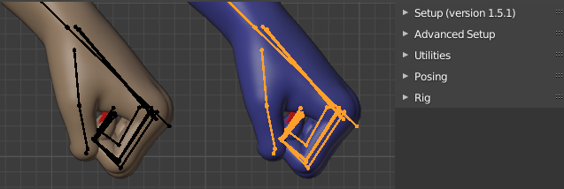
If we replace the action of the original armature nothing happens, because the finger bones are still driven by rig properties. But if we import the character again (this time with blue skin) and load the new action, it will move in the same way as the old character, although it does not have any bone drivers.

Since the unwinded action only involves bone rotations and no drivers, it should work if it is exported to other applications.

This is the first version of this tool. There are at least two improvements that immediately come to mind:

1. Some adjustments are necessary if the driven bones have been made posable with the Make All Bones Posable tool.

2. The same rig property can drive both bone rotations and shapekeys, and that case should be handled too.

In the near future these issue will be addressed.


asdf


asdf


asdf


adsf


asdf

Monday, December 7, 2020

Decals

 Decals are a common way to add localized details to your textures. For humans, decals can be used to add e.g. tattoos, bruises and wounds, but decals can of course be equally well used on inanimate objects. You can add decals in DAZ Studio, but I never understood how it works, and for me it is much simpler to do it in Blender, especially if you want the decals to follow the mesh when animating. To make it easier to add decals directly in Blender, I made a new button called Make Decal, which is found towards the bottom of the Materials section.

When we press Make Decal, a file selector appers where we can choose the image file that contains the decal. The tool adds it to the active material, so make sure that the right material is active. The active material is displayed at the top of the list to the right. The other checkboxes lists the nodes that we want to add the decal to. In this case we have a material with a principled node, and want to add the decal to the base color and to the bump node.

Here is the node tree,slightly edited for clarity. Two new node groups have been added before the principled and bump nodes. The Influence input can be used to animate the decals, e.g. a stab wound should only be visible after the character has been stabbed.

It may be necessary to edit some of the decal node groups. To do that, select the node group and open it by hitting tab. E.g., we may want to change the texture for the bump decal and change the color space to Non-Color. It is assumed that the texture has an alpha channel, but if we have a separate opacity texture we need to add an extra texture node for that and use its color output as alpha. 
The tool also creates an empty with the same name as the texture. By moving, rotating and scaling this empty we can control the location of the decal. Initially the decal covers almost the entire torso material, so we need to scale down the empty.

To place the empty correctly, we turn on snapping (the magnet icon at the top), snap to face, and make sure that Backface Culling and Align Rotation to Target are enabled.

We can now move the decal into place

To make sure that the decal stays put when we pose the character, we make a vertex parent.
And now the decal stays in place when the character is posed.

This is a very neat and light-weight way to add decals to your meshes, but it has an important limitation: the decal is only added to a single material. So if we want to place the decal so it crosses the boundary between two different materials, parts of it are cut off. To deal with this case, a little more work is necessary.
The idea is to make a separate mesh on which we place the decal. In edit mode, duplicate vertices around the shoulder and then separate them into a new shoulder pad mesh, which we rename to Tattoo.

The tattoo mesh inherits the armature modifier and vertex groups from the original mesh. However, most of the vertex groups only involve vertices far away from the tattoo, so they are of no use here. To quickly remove empty vertex groups, we can use the Advanced Setup > Mesh > Prune Vertex Groups tool. Now only the relevant vertex groups remain.

We want the shoulder pad to stay on top of the body, so we add a shrinkwrap modifier with a small offset. This can be done by selecting the body and using the Setup > Morphs > Add Shrinkwrap tool, or directly by adding a shringwrap modifier to the tattoo mesh.

The tattoo mesh also inherits the UV coordinates from the body mesh, but they are not suitable here since there is seam where we want to place the decal. In edit mode, clear all seams and then mark a new seam in a region where the decal will not cross, e.g. under the arm.

Then we unwrap the tattoo mesh. The UV coordinates are now nicely laid out and there are no seams in the region where we want to place the decal.

Next we go to the Shaders tab and make some changes to the material.

A freshly created material contains a principled node and an output node, which is good in our case. Turn down Alpha to zero. If the render engine is Eevee, we must change some material settings. Enable Backface Culling, set the Blend Mode to Alpha Clip or Alpha Hash, and turn off shadows by setting Shadow Mode to None

Now press Make Decal with the tattoo mesh selected, and enable Principled Base Color only. The decal node group appears. Since there is no ingoing texture this time, the Color output is connected to the Base Color socket rather than the Combined output. We must also manually connect the Alpha output to the Alpha socket of the principled node.

And now we can place the decal on the shoulder. Unfortunately, this decal looks more like a plastic sticker than like a real tattoo. How to fix that is left as an exercise for the Blender gurus out there.

Finally we have to vertex parent the empty, either to the tattoo mesh or to the underlying body, to make sure that the decal follows the mesh when posed.

Friday, December 4, 2020

Morph Transfer Progress

Something that happens quite often to me is that I have a finished character with merged geografts, and then realize that I want to add some more morphs to it. This cannot be done directly, because by merging geografts the vertex numbers change, and it is no longer possible to add morphs. A long time ago Engetudouiti came up with a work-around: reload the body and geograft, add morphs to the reloaded meshes, and then transfer the shapekeys to the character mesh. The problem is that morph transfer is painfully slow, because it uses the data transfer modifier many times. So I came up with some improvements which makes morph transfer much faster, although they do not work in all cases.

After we have reloaded the character and merged rigs and renamed the meshes for clarity, the situation typically looks like this. We want to load morphs to the reloaded body and geograft, and then transfer them to the merged mesh.

The first step is to delete the reloaded armature, and reparent the body and geograft meshes to the original armature. Parenting is necessary to create drivers for the morphs. It is also needed if we want to load the standard morphs (face units, expressions and visemes), because the importer decides which type of character it is dealing with by looking at the children's fingerprints. (The fingerprint of a mesh is the number of vertices, edges, and faces, and is a reasonably safe way to identify the character). The merged mesh does not have a known fingerprint but the reloaded body has, so standard morphs can imported.

If we are dealing with a Genesis 3 or Genesis 8 character, we are done already. In this case the morphs are face rig poses, which deform the merged mesh as well.

However, if the morphs involve shapekeys, these must be transferred to the merged mesh using the Transfer JCMs or Transfer Other Shapekeys buttons. With the source mesh (which we transfer from) active and the target mesh or meshes (which we transfer to) selected, press Transfer Other Shapekeys.

At the top of the pop-up dialog there is a new option which determines the transfer method. It can take on four different values:

  • General: This is the old transfer method using the data transfer modifier. It is very slow but works well in general if you have the patience.
  • Nearest Vertex: Transfer shapekeys from the nearest vertex on the source mesh. This usually works well to transfer shapekeys to clothes and is the default. Computing the nearest vertex involves a slow step because a matrix of distances between all vertex pairs is computed, but this step is only done once for each target mesh, and once it is done the actual morph transfer is fast. Moreover, this matrix is calculated with Numpy which is much faster than pure Python.
  • Body: Only transfer between the first vertices, until a vertex with changed location is encountered. This works for shapekeys on the body that do not involve the geograft, because the merged vertices have higher vertex number than the original ones. This method is very fast when it works.
  • Geograft: Transfer shapekeys to the nearest vertex of the target mesh. Note the difference to the Nearest Vertex method. There each target vertex is paired with a source vertex, here each source vertex is paired with a target vertex, and nothing is transferred to unpaired target vertices. Use this to transfer shapekeys from the geograft to the merged mesh. Performance is the same as for the Nearest Vertex Method.

First we transfer a shapekey from the body mesh to the merged mesh. In the pop-up dialog, chose the Body transfer method. Also make sure that Use Driver is enabled, so we can control the shapekeys from the rig.

Next we transfer shapekeys from the geograft, so this time we choose the Geograft method. Here it is important that Ignore Rigidity Groups is enabled.

Both types of shapekeys have been transferred to the merged mesh and can be controlled from the Custom Morphs panel.

The main application of the transfer tools is to transfer Joint Corrective Morphs (JCMs) from a character to her clothes. Here we have imported G8F with the Bardot outfit, and loaded the JCMs to her body. With the skirt selected and the body active, press Transfer JCMs.

Choose the Nearest Vertex method since we are transferring morphs to clothes. We only select the morphs that are interesting for the skirt, i.e. the abdomen, pelvis and thigh JCMs. Shin and Foot JCMs would affect the skirt, but that is not desirable. It is only necessary to transfer morphs to tight-fitting clothes, whereas the transfer to loose-fitting clothes may result in undesirable artefacts. The skirt only fits the body tightly around the hips and upper thighs, so only those morphs should be transferred.

Also the thigh morphs create problems at the bottom of the skirt, where it is far away from the body.

To avoid such artefacts, we can control the influence of the shapekey with a vertex group, as shown above. With this trick the problems at the bottom of the skirt are gone.

Corrective morphs are usually not by themselves so important for clothes, except for very tight-fitting ones. The main reason to transfer morphs is to keep the clothes on top of the skin, to avoid that skin pokes through. Alessandro Padovani pointed out that there is an alternative method to achieve this, which circumvents the need to transfer morphs altogether: the shrinkwrap modifier. The button Add Shrinkwrap adds a shrinkwrap modifier to the selected meshes, keeping it above the active mesh. This button was already available in the Visibility section, but is now available next to the transfer morphs buttons as an alternative.

Select the body mesh. In the pop-up dialog we choose which meshes that need to stay on top of the skin.

A shrinkwrap modifier now appears in the modifiers tab.

Here is how the Bardot top behaves when posed, without and with the shrinkwrap.


Sunday, November 29, 2020

Preparing Mesh Hair

Tonight I ran into some trouble when I was trying to convert the hair below to particles, and added some tools to deal with it.

At the top of the Hair section we now find the Print Statitistics button. This tool already existed in the Low-poly section, but it is convenient to duplicate it here because we want to keep track of how heavy the hair is before converting.  This beauty is a real heavy-weight with over half a million vertices.

  Verts: 566945, Edges: 419810, Faces: 139156

We don't want to convert such a heavy mesh to particles, both because conversion times grows fast with the number of particles (at least quadratically), and the resulting particle hair would be very unwieldy. To deal with that problem, there is a new tool called Select Strands By Size, which groups strands according to the number of faces and selects the groups that we want.

When we press the button a dialog appears where we can select the sizes. It takes some time before the dialog appears, because the mesh must first be analyzed and the faces grouped by size. In this case there are four groups, with 0, 40, 44 and 1156 vertices. Select that latter, which is not a strand but the hair cap.
Separate the selected vertices to a new object which we rename to Scalp. We also changed the viewport color of the hair cap material so we can distinguish it from the hair.
Invoke Select Strands By Size once again, and select the groups with 40 and 44 faces. We want to delete the strands with size 0, but for some reason nothing is selected when we select that group. Therefore we select the other two groups and then invert the selection.
Here is the inverted selection which consists of stray verts only, and the hair after the stray verts have been deleted. We can check the size again with the Print Statistics tool:

   Verts: 282860, Edges: 417430, Faces: 138000

Half of the vertices have disappeared, but the number of edges and faces has only decreased a little, probably because the scalp mesh was separated.

The hair mesh is still huge with 138,000 faces, and will take a very long time to convert. A reasonable size is 30,000 faces or less. To reach that number, we now Select Random Strands with a fraction = 0.8. This will select 80% of the remaining faces at random. Note that the semantics of this tool has changed; previously we specified the fraction of vertices that were not selected.

Delete the selected vertices and toggle out of edit mode. Again we check the size of the mesh with the Print Statistics tool:

Verts: 57342, Edges: 84623, Faces: 27976

The mesh now weighs in at almost 28,000 faces, which can be converted in a reasonable time, ca five minutes on my computer. It is a good idea to check the hair from different angles to ensure that there are no large bald spots.

Now the mesh is prepared for conversion to particle hair.

Select the hair and the scalp mesh, and press Make Hair. The meshes must be selected in the right order, with the hair active. For convenience the two meshes are listed below the button, so we can easily tell if they have been selected in the wrong order.

If we use the default options, the result is an unpleasant surprise.

The reason for this behavior is that the strands are oriented bottom-up in UV space. The UV coordinates are used as coordinates along the strands. The default assumption is that the strands are oriented vertically in UV space, with the roots at the top and the tips at the bottom. This has been the case in almost every hair that I have encountered so far, e.g. the Toulouse hair that comes with DAZ Studio. However, in this case the strands are oriented bottom-up, so the roots are close to the bottom of the UV.

To fix this, there is a new option in the pop-up dialog, Strand Orientation, which can take on four different values, depending on the orientation of the strands in UV space.

  • Top-Down: Vertically in UV space, with roots at the top (default).
  • Bottom-Up: Vertically in UV space, with roots at the bottom.
  • Left-Right: Horizontally in UV space, with roots to the left.
  • Right-Left: Horizontally in UV space, with roots to the right.

We select Sheet in the Create section and set Strand Orientation to Bottom-Up. We also resize the hair to a hair length of 40.

And here is the particle hair, in the viewport and rendered.