Geometry nodes is a powerful way to manipulate meshes that was introduced in Blender 3.1. They are used in the development version of the DAZ Importer as an alternative way to import geoshells and geografts from DAZ Studio. This could not have happened without the help of commenter Midnight Arrow, who explained to me about geometry nodes in general, and how they could be used in these specific cases.
This blog post describes how to import a geoshell as a geometry node setup in Blender. Later posts will cover geografts and how to import characters with shells and geografts directly from the DAZ database, without taking the detour over DAZ Studio.
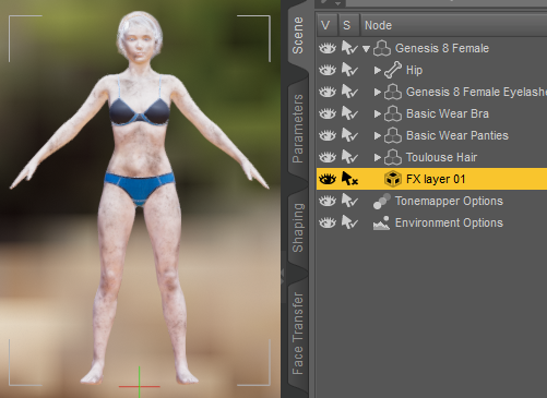
Here we have a dirty character in DAZ Studio. The dirt is added with a geoshell called FX layer 01.
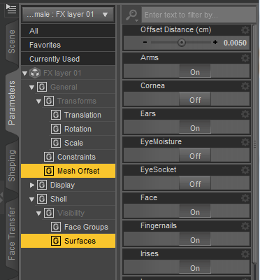
In the Parameters tab we find that the shell is pushed away from the main mesh by a small distance; Offset Distance = 0.0050 cm. There is also the list of surfaces affected by the shell.
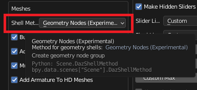
By default a shell in DAZ Studio corresponds to a node group in the Blender materials. To generate a geometry node tree instead, we change the global setting Shell Method to Geometry Nodes (Experimental).
The body mesh looks strange in the viewport. This is because the shell becomes a second mesh which is located in almost the same place as the body mesh.
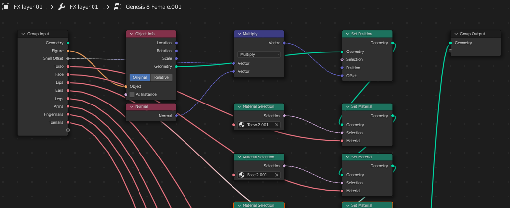
The shell by itself is an empty mesh, i.e. it does not have any vertices, edges or faces. But it has materials and a nodes modifier which generates the mesh. The modifer has a number of parameters:
- Figure: The mesh that the shell copies.
- Shell Offset: This is the Offset Distance parameter in DAZ Studio. In this case it is 0.005 cm = 0.00005 m.
- Material slots: There is an entry for each material where the shell is visible and not totally transparent.
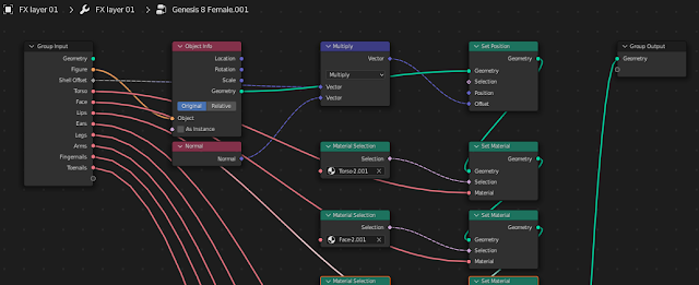
We can inspect the node tree in the geometry node editor. The nodes modifier generates a new mesh where the body materials are replaced by the shell materials.
Here is the shell mesh by itself, with viewport shading set to sold and rendered, respectively.
Here is a rendered example, with the two different Shell Method settings.
There is a problem with previewing the shell materials. Geometry nodes
require that the materials pick up the UV maps with named UV Set or
Attribute nodes, but Blender 's previewer only works if we use a Texture Coordinate node for that.
Here is how one of the shell materials is previewed. Since it uses a Attribute node, the previewer doesn't find the UV coordinates but uses the value of the first pixel at (0,0).
Fortunately, we can use the new Make Palette tool to preview the shell materials. This tool was originally intended for storing materials for the new asset browser, but it can also be used for previewing. Select the shell in the outliner and make a palette.
Here is the palette viewed from above, in solid and rendered viewport shading. The shell mesh has nine materials, but there are only eight material slots in the nodes modifier. This is because the Irises material (material number 8) is visible but purely transparent.